Kampstraße 47, Dresdner Bank, Dortmund

-
Result
-
Extracting Data from the Model
THE BUILDING
Designed 40 years ago by the famous German architect Harald Deilmann, the former Dresdner Bank headquarters in Dortmund is under historical protection due to its contemporary, pop-art inspired architecture.

Kampstraße 47, 3D Model (1974), Harald Deilmann

Harald Deilmann by Andy Warhol
THE TASK
Creation of a detailed BIM model of the former Dresdner Bank headquarters in Dortmund. The Model would serve as a virtual copy of the existing building to be used for facility managing, maintenance, reconstruction and demolition purposes.
WHY BIM
There are numerous benefits of BIM in all phases of the the design and construction process. In this particular case, the building would be subdivided and rented out to different companies. During the renovation phase exact quantities would be required to receive the best possible offers. Later on, the data would be be used for facility management purposes, like rental- or relocation management, fire protection, and for interior design.
-
Working with a complete model instead of thousands of plans
-
-
Base for reconstruction and new construction with easy implementation of changes
-
Precise cost estimation for tendering
-
Information about volumes (graphic), material and prices (alphanumeric), room information (usage, floor and wall covering)
-
Demolition management – waste disposal, (Calculation of volumes)
-
Generation of sections, views, perspectives, working drawings, calculation models, position plans, formwork drawings, reinforcement drawings, etc. straight from the BIM model
-
Collision control of reinforcement nad HVAC
-
Information for facility management, fire safety, building maintenance, cleaning, space allocation and changes
-
Implementation in city and Infrastructural planning, catastrophe management, ecological fingerprint, cadastral information.
TECHNOLOGY
We were using a very powerful software, that allowed us to manage the huge amount of data. The first step was to set up a proper building structure with the “Building Manager”. Through the architectural functions of Allplan we defined then the intelligent elements like Walls, Slabs and columns. Since Allplan creates parallel to the BIM model also an exact working drawing of each floor, it was easy for us to crosscheck the results with the original plans at any time.
The model was then saved on the BIM plus platform which is actually a cloud server and allows all participants to access the model. The data is saved there in the neutral IFC format, so that other planners like HVAC – or Construction engineers can add their data in any BIM compatible format.
OUTPUT DATA
Scanned hand drawings from the seventies of the last century in PDF format:
-
More than 2500 drawings
-
Over 70 GB
-
DWG files

PROCESS
First site visit:
-
Project Structure in Allplan
-
Allplan–levels definition
-
Drawing settings, materials
-
Wizard
-
User attributes definition
-
Communicate with the client how the structural elements shall be modeled
Second site visit:
Final corrections and model adjustments
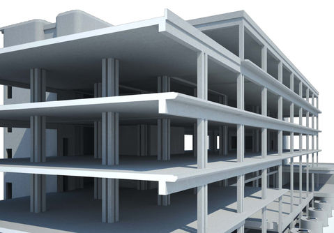
Structure – Detail level 1:1
The detailed level of the structure model is 1:1. The building consist of underground garage levels and 7 office floorplans. Outstanding space is the atrium with a massive ladder, which looks like its floating. Another element is a passage through the building which looks like a street with outdoor lamps and plant pots. It’s surrounded by pavilion type volumes that lead to the 2nd floor and a big terrace.

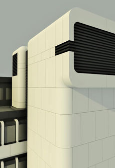
Concrete Facade – Detail level 1:1
The detailed level of the structure model is 1:1. All the concrete panels were prefabricated and marked with an identity number. The elements around on the 1st floor define the atrium and make the former bank an unique building. Luckily there was a typical panel, but also more than 70 single concrete elements with different double curvature of the geometry.

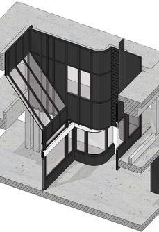
Metal Facade – Detail level 1:1
The detailed level of the structure model is 1:100. Some of the old drawings were missing and part of the façade was modeled based on pictures from the site visit. It’s designed in anthracite color and serves as a background of the white concrete facade. The metal façade serves as a connection between the building and the visitors, defining all the entrances

RESULT
We made this experiment and compared views from the 3D model with some photos from our site visits.
EXTRACTING DATA FROM THE MODEL
-
Automatic views, sections, facades and all the necessary documents
-
Automatic labeling
-
Automatic quantity takeoffs
-
Automatic updates in the drawings when the model is changed
-
Visualization
-
Base for a photo-realistic renderings in specialized software
-
Static and dynamic calculations based on the model using specialized programs


